Engineering selection based on payload dynamics, line-of-sight accuracy, wind load, integration and acceptance testing
A pan-tilt unit (PTU) for long-range surveillance should not be selected by payload weight alone. The complete decision depends on payload geometry, center of gravity, moment of inertia, wind area, motion profile, line-of-sight stability, interfaces, installation stiffness and the acceptance evidence required for the installed system.
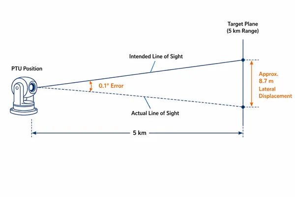
This distinction matters most when the PTU carries a long-focal-length visible camera, thermal imager, laser rangefinder or multisensor enclosure, or when radar coordinates are used to cue the camera. In those applications, small mechanical, calibration and timing errors can become a large miss distance at the target.
The objective is therefore not to find the fastest or highest-capacity platform. It is to prove that the installed assembly can move, settle, point and track the real payload within the required line-of-sight error under the specified environment and duty cycle.
| Quick answer: Start with the complete payload load case. Then define motion quality, pointing and tracking accuracy, wind and structural conditions, interfaces and time synchronization, and the FAT/SAT evidence. Compare PTU families only after those requirements are frozen. |
1. Start With the Complete Payload Load Case
Payload weight is only the first input. Two assemblies with the same mass can impose very different torque, inertia, wind and clearance requirements. The supplier needs the complete installed configuration, including brackets, housings, cable loops, illuminators, laser modules and any item that moves with the payload.
| Load-case input |
What the supplier needs |
| Mass |
Total installed mass, including camera, lens, thermal module, laser, housing, brackets, cable loops and accessories. |
| Center of gravity |
Coordinates relative to the pan and tilt axes in every relevant payload configuration. |
| Dimensions and envelope |
Outer dimensions, lens extension, service clearance, travel envelope and possible collision points. |
| Moment of inertia |
Measured or calculated inertia about both axes, or sufficient CAD data for the supplier to calculate it. |
| Projected wind area |
Frontal and side area at representative azimuth and elevation angles, including covers and sunshields. |
| Cable and hose forces |
Routing, bend radius, torsion, drag, connector position and continuous-rotation requirements. |
| Mounting interface |
Bolt pattern, adapter geometry, stiffness, flatness, installation orientation and available structure. |
| Configuration changes |
Lens travel, filter changes, retractable parts, moving accessories or alternate sensor combinations. |
A serious request for quotation should include a payload CAD model or a dimensioned drawing that supports load-case calculation. A statement such as “camera weight: 30 kg” is not sufficient for engineering approval.
2. Center of Gravity Determines Continuous Torque
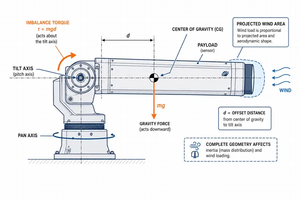
When the payload center of gravity is offset from the tilt axis, gravity creates a continuous imbalance torque. The motor, gearbox, bearings and structure must carry this load before acceleration, friction or wind is considered.
| Illustrative first-order calculation: Imbalance torque T = payload mass m x gravitational acceleration g x center-of-gravity offset d. For a 30 kg payload with a 0.30 m offset, T is approximately 30 x 9.81 x 0.30 = 88 N·m. This is not a product rating and does not include friction, acceleration, wind or engineering margin. |
How to Select a Pan-Tilt Unit for Long-Range EO/IR and Radar-Cued Tracking
Counterbalancing can reduce continuous drive load, improve low-speed control and preserve thermal margin. The balance method must still be checked across the required tilt travel, lens extension and maintenance envelope. A counterweight that improves balance but causes interference or excessive inertia is not an acceptable solution.
3. Moment of Inertia Controls Acceleration and Stopping
Moment of inertia describes how strongly the payload resists angular acceleration. Mass positioned far from the rotation axis contributes disproportionately, which is why a long enclosure may be harder to accelerate and settle than a compact payload of the same weight.
| Dynamic relationship: Acceleration torque = moment of inertia x angular acceleration. The required drive torque also includes imbalance, friction, wind disturbance and a defined engineering margin. |
The useful procurement measure is not unloaded maximum speed. It is the time required to move through a representative angle with the actual or dynamically equivalent payload and then remain inside the specified pointing-error band without excessive overshoot, oscillation or thermal derating.
4. Maximum Slew Speed Is Not Tracking Quality
A PTU can rotate quickly and still perform poorly when tracking a slow, distant or maneuvering target. Speed, acceleration, low-speed smoothness and settling behaviour should be specified and tested separately.
| Parameter |
Why it matters |
| Maximum slew speed |
Gross repositioning time; it does not prove settling, smoothness or tracking accuracy. |
| Minimum stable speed |
Ability to follow slow angular motion without stick-slip, stepping, hunting or visible image disturbance. |
| Speed resolution |
How finely the controller can match the target angular rate. |
| Acceleration and deceleration |
Commanded motion profile, peak torque, overshoot risk and structural excitation. |
| Settling time |
Time from the command or motion end until the line of sight remains within a defined error band. |
| Duty cycle |
Permitted operating pattern, ambient condition, continuous-motion limit and thermal derating. |
| Reversal behaviour |
Backlash, deadband and transient error when direction changes. |
| Buyer test request: Require a move-and-settle test using representative angles, the production controller and the actual or dynamically equivalent payload. Define the error band, dwell period and thermal state before testing. |
5. PTU Accuracy Terms Defined: Resolution vs Repeatability vs Pointing Accuracy
These terms are often used interchangeably, but they measure different properties. A fine command increment or encoder count does not prove that the optical line of sight will reach the commanded direction accurately, repeatedly or without jitter.
| PTU accuracy term |
Definition |
| Command resolution |
Smallest position increment the controller can request or represent. |
| Encoder resolution |
Smallest position increment measured by the feedback device. |
| Absolute pointing accuracy |
Difference between commanded and actual line of sight across the operating envelope. |
| Repeatability |
Ability to return to the same line of sight under stated direction, load and environmental conditions. |
| Backlash / deadband |
Lost motion or command reversal interval caused by gearing, compliance or control logic. |
| Settling band |
Permitted residual pointing error after a move and the time for which it must remain inside the band. |
| Line-of-sight jitter |
Short-term angular or image motion while stationary or tracking. |
A system may advertise very fine encoder resolution while still having poor absolute pointing accuracy because of gearbox error, assembly tolerance, mast deflection, boresight offset or thermal drift. The specification should state the required system outcome and the test method for each term.
How to Select a Pan-Tilt Unit for Long-Range EO/IR and Radar-Cued Tracking
6. Long-Range Optics Magnify Mechanical and Calibration Error
Long focal length narrows the field of view. That improves target detail, but it also makes line-of-sight error, structural vibration and backlash more visible. A radar cue that places the target inside a wide field of view may miss the target completely after the camera changes to a narrow field of view.
Connect the optical requirement to the PTU requirement by defining:
- the required field of view at detection, recognition and identification stages;
- the permitted target displacement within the narrowest operational field of view;
- the allowable line-of-sight jitter during stationary observation and continuous tracking;
- the camera or gimbal image-stabilization capability and the conditions under which it remains effective;
- zoom-state feedback and whether the control system changes cueing or tracking gains with focal length;
- the effect of lens travel, focus movement, filters and moving accessories on center of gravity and boresight.
For payload context, review Midradar’selectro-optical product families. Final PTU approval still requires the actual payload geometry and optical operating modes.
7. Wind Load, Mounting Stiffness and Structural Deflection
Outdoor payloads act like sails. Aerodynamic force rises approximately with the square of wind speed, while the resulting torque depends on projected area, drag coefficient and distance from the rotation axis. The PTU cannot compensate for a flexible mast, weak adapter or moving weather cover.
| Illustrative first-order relationship: Wind force may be estimated as F = 0.5 x air density x drag coefficient x projected area x wind speed². The torque contribution depends on the force lever arm. Final design requires the actual geometry, installation condition and specified operational and survival wind limits. |
The structural review should include:
- maximum operational wind for full pointing and tracking performance;
- survival wind when the unit is parked, locked or de-energized;
- projected area at representative pan and tilt angles;
- mast, tower, adapter, fastener and mounting-plate stiffness;
- natural frequencies and possible excitation by motor commands, wind or vehicle vibration;
- cable drag, housing flex, lens-support stiffness and weather-cover movement;
- image-based jitter measured with the real focal length and representative wind condition.
A mechanically strong PTU mounted on a flexible pole can still produce unusable imagery. Treat the foundation, mast, adapter, PTU and payload as one line-of-sight structure.
8. Radar-Cued Tracking Requires an End-to-End Error Budget
Radar-to-camera cueing combines multiple coordinate systems, time references and mechanical elements. The final line-of-sight error is a system property; it cannot be inferred from the PTU encoder specification alone.
| Error source |
Typical contribution |
Verification action |
| Radar measurement |
Range, azimuth, elevation, tracker filtering and target-state uncertainty. |
Confirm exported accuracy or covariance, update behaviour and test conditions. |
| Survey and alignment |
Radar position, installation orientation, north reference and mast survey. |
Use surveyed coordinates and document orientation conventions and sign definitions. |
| Coordinate conversion |
Geodetic, map, radar, local Cartesian, PTU and camera frames. |
Document datum, altitude reference, units, formulas and test cases. |
| Prediction and latency |
Target motion during sensor, network, processing and actuation delay. |
Measure timestamps and latency distribution; validate prediction against representative target motion. |
| PTU mechanics and control |
Absolute accuracy, repeatability, backlash, settling and feedback delay. |
Test the actual payload over multiple angles, directions, speeds and thermal states. |
| Camera boresight |
Mechanical alignment, internal gimbal offset, lens state and thermal drift. |
Calibrate at defined zoom states and record the correction model. |
| Structure and environment |
Mast deflection, vibration, wind, vehicle motion and thermal movement. |
Validate with surveyed targets or cooperative targets under relevant conditions. |
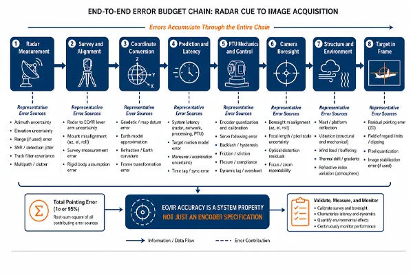
How to Select a Pan-Tilt Unit for Long-Range EO/IR and Radar-Cued Tracking
Commissioning should use surveyed reference points or cooperative targets and should cover multiple azimuth and elevation angles. A correction measured at one direction may not represent the complete operating envelope.
| Need a project-specific radar-to-camera error budget? Send the radar accuracy, coordinate-frame definitions, sensor locations, latency data, PTU performance, camera boresight information and required target-in-frame criterion to Midradar’s integration team. |
9. Interfaces, Position Feedback and Time Synchronization
The interface specification must describe functional behaviour, not only the transport or protocol name. Ethernet, RS-422/485, Pelco-D/P, ONVIF and manufacturer APIs can all be useful, but none of those labels alone proves radar-cueing performance.
For integrated tracking, verify:
- absolute pan and tilt positioning, not only left/right/up/down rate commands;
- real-time position feedback with timestamps, documented units and sign conventions;
- command acknowledgement, fault codes, health reporting and recovery behaviour;
- configurable acceleration, deceleration, speed limits, travel limits and emergency stop;
- time synchronization through NTP, PTP or another defined system clock;
- API access to calibration offsets, coordinate mapping and controller status;
- authentication, role control, secure transport, logging and software-version management.
For communication-path and rapid-response design, use the separate radar-vision PTZ response guide. This article remains focused on mechanical selection, line-of-sight accuracy and acceptance evidence.
10. Environmental and Lifecycle Requirements
An IP rating describes enclosure protection against solid objects and water under defined tests. It does not by itself prove salt-fog resistance, long-term corrosion protection, de-icing, wind performance, shock survival or reliable cold start.
| Requirement |
Questions to specify |
| Ingress protection |
Applicable IEC 60529 level and whether it covers the complete installed system, connectors and cable entries. |
| Temperature |
Operating, storage and cold-start temperatures; heaters, fans, warm-up time and thermal-derating behaviour. |
| Salt fog / corrosion |
Materials, coating system, fasteners, connector protection, drainage and applicable cyclic salt-mist test. |
| Wind |
Operational and survival limits, stow position, braking/locking and performance reduction with wind speed. |
| Shock and vibration |
Installation-specific spectra, axes, duration, mounting condition and post-test functional checks. |
| Rain, dust, ice and condensation |
Wipers or covers, drainage, anti-icing, heaters, seals and maintenance requirements. |
| Power and EMC |
Voltage range, inrush, grounding, surge/lightning protection, emissions and immunity requirements. |
| Lifecycle support |
Maintenance intervals, lubrication, calibration, spares, software support, obsolescence and repair turnaround. |
11. Define Factory and Site Acceptance Tests Before Award
A useful acceptance program combines mechanical, control, optical and system-level measurements. The test setup, payload, environmental limits, measurement method, pass/fail criteria, data to retain and retest procedure should be agreed before contract award.
| Test |
Suggested measurement |
Stage |
| Payload verification |
Measure actual mass, center of gravity, dimensions, projected wind area and cable routing. |
Factory |
| Slew and settle |
Move through agreed angles and measure time to remain inside the specified line-of-sight band. |
Factory |
| Minimum-speed tracking |
Measure image smoothness and angular-rate stability at the lowest required speed. |
Factory |
| Reversal and repeatability |
Approach reference angles from both directions and quantify deadband and return error. |
Factory |
| Absolute pointing |
Compare commanded and measured line of sight across representative pan/tilt positions. |
Factory / Site |
| Thermal operation |
Repeat critical tests after cold start, warm-up and sustained duty where required. |
Factory |
| Interface and feedback |
Verify commands, timestamps, status, faults, limits, calibration access and software versions. |
Factory / Site |
| Boresight calibration |
Align the PTU/camera system to surveyed references at defined zoom states. |
Site |
| Radar cueing |
Measure acquisition time and target-in-frame performance using representative target motion. |
Site |
| Wind / structural response |
Measure line-of-sight stability under agreed wind or equivalent disturbance conditions. |
Site |
| Lifecycle deliverables |
Confirm manuals, drawings, interface documents, spares, training, data logs and support plan. |
Factory / Site |
| Downloadable project tool: Use the Midradar PTU RFQ Data Sheet and FAT/SAT checklist to collect the engineering basis before requesting a binding recommendation. Provide the information you have; Midradar can identify missing fields. |
12. Use a Structured PTU Selection Workflow
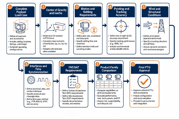
How to Select a Pan-Tilt Unit for Long-Range EO/IR and Radar-Cued Tracking
The workflow is the article’s decision map. Sections 1-3 define the payload and mechanical load case; Section 4 freezes motion performance; Sections 5-8 define line-of-sight accuracy and the radar-cueing error budget; Sections 7 and 10 establish environmental and structural limits; Section 9 freezes interfaces and timing; Section 11 defines FAT/SAT evidence. Only then should Sections 14-15 be used to compare PTU families and issue a complete RFQ.
This sequence prevents a project from selecting a PTU by nominal payload capacity and discovering later that the installed assembly cannot settle, track slowly, maintain narrow-field-of-view stability, survive the environment or integrate with the control system.
13. Select the Product Family Only After the Load Case Is Approved
Product-family mapping should follow the engineering screen, not replace it. Compare the actual payload mass, center of gravity, inertia, projected wind area, speed and settling requirement, pointing-error budget, environmental class, interfaces and duty cycle against the supplier’s approved load envelope. A nominal payload rating is only one input.
Where a Midradar PTU family is considered, request written confirmation against the completed RFQ data sheet and the proposed mounting structure. Final approval should identify the exact controller, encoder configuration, cable arrangement, environmental options and acceptance test.
14. Use the PTU RFQ Data Sheet as the Engineering Handover
Move the full payload, geometry, inertia, wind, interface and FAT/SAT fields into the editable PTU RFQ Data Sheet. The article should explain why each input matters; the worksheet should capture project values, supplier responses and unresolved assumptions. Do not approve a PTU from a statement such as “camera weight: 30 kg.”
Conclusion
A PTU should be selected as part of a complete line-of-sight system, not as an isolated motorized mount. Payload weight, center of gravity, inertia, wind area, structural stiffness, motion profile, optical field of view, pointing error, interfaces and acceptance evidence all influence whether the installed system will work.
For radar-cued EO/IR tracking, the decisive question is not “How many kilograms can the PTU carry?” It is “Can the installed system move, settle, point and track the real payload within the required line-of-sight error under the specified environment and duty cycle?”
Request a PTU Sizing and Radar-Cueing Review
Send Midradar the completed RFQ data sheet, payload CAD or dimensions, center-of-gravity information, wind and mounting conditions, required motion and accuracy, interface boundary and FAT/SAT expectations. The technical team can then review the mechanical load case, integration risks and the evidence required before model approval.
Use Midradar’s technical support and customization resources or contact the project team to submit the data package.
FAQ
Can a PTU be selected only by maximum payload weight?
No. Weight is only one input. Center-of-gravity offset, inertia, wind area, acceleration, duty cycle, structural stiffness and line-of-sight requirements can be equally important.
What is more important: pointing accuracy or repeatability?
Both are required for radar cueing. Accuracy determines how close the camera points to the commanded line of sight; repeatability determines whether it returns consistently. Neither replaces system-level survey, boresight calibration and validation.
Why does a long lens make PTU selection harder?
A long lens usually increases payload length, inertia and wind area while narrowing the field of view. Mechanical vibration, backlash and small angular errors therefore become more visible and more likely to move the target outside the image.
Should the radar, PTU and video system use the same time source?
They should use synchronized time or a documented timing architecture. Accurate timestamps reduce prediction and coordinate-conversion error, especially for fast or maneuvering targets.
What is the most useful PTU acceptance test?
The most informative test is an end-to-end move, settle and radar-cueing test with the actual payload. It should measure line-of-sight error, target acquisition time, repeatability and tracking performance under agreed conditions.



 13:42
13:42