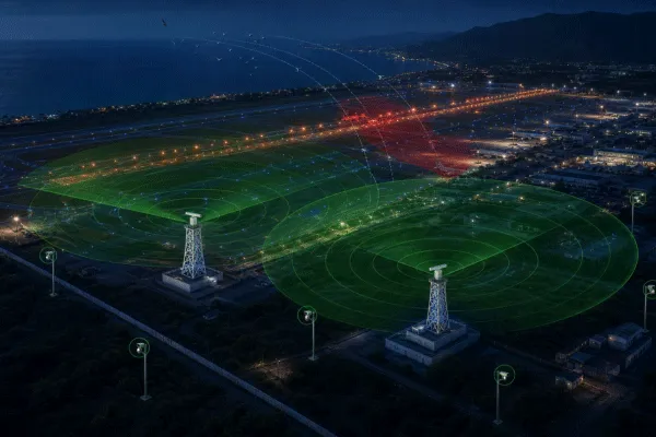
Online Thermal Monitoring for a Chemical Industry Park
Online Thermal Monitoring for a Chemical Industry Park
How Thermal Imaging, Visible-Light Verification and Centralized Alarms Support Proactive Industrial Safety
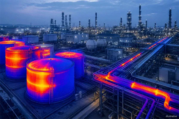
Large chemical industry parks contain process units, storage tanks, pipelines, valves, pumps, electrical systems and hazardous-material handling areas distributed across extensive sites. Many of these assets operate continuously and may develop abnormal thermal conditions before a visible failure, fire or production interruption occurs.
At the Yantai Development Zone Chemical Industry Park in Shandong, China, the publicly available case description identifies a need for more continuous, visible and intelligent safety supervision across a complex industrial environment. The objective was to detect abnormal temperature conditions earlier, support visual verification and strengthen centralized safety management.
The public case page states that the park introduced an industrial online thermal monitoring and hazardous chemical safety solution built around thermal imaging, intelligent analysis, visual verification, alarm linkage and centralized management.
The public description presents the project as a shift from fragmented and periodic observation toward continuous monitoring, earlier warning and more centralized review. It does not disclose the exact device models, quantities, installation positions, commissioning period or measured operational KPIs.
Online Thermal Monitoring for a Chemical Industry Park (Illustrative)
Project Snapshot
Artículo
Project Information
Industria
Chemical production and hazardous-material management
Location
Yantai, Shandong, China
Site Type
Large chemical industry park
Publicly Described Environment
High-temperature equipment, storage facilities, long-distance pipelines, outdoor exposure and multiple critical points across a large chemical park
Core Challenge
Periodic manual inspection could not provide continuous visibility of developing thermal abnormalities
Monitoring Method
Infrared thermal imaging combined with visible-light verification
Publicly Described Architecture
Connected field devices, alarm functions and management terminals operating through a networked platform
Main Functions
Thermal monitoring, abnormal-temperature detection, alarm linkage, event verification and historical record management
Publicly Described Outcome
Continuous monitoring, earlier warning and more centralized safety-management visibility
Disclosure
Specific equipment quantities, installation positions and operational KPIs have not been publicly disclosed
Background
Chemical production environments present a combination of process, equipment and environmental risks.
Storage tanks, reactors, heat exchangers, pumps, motors, bearings, electrical cabinets and long-distance pipelines may all exhibit abnormal temperature changes when operating conditions deteriorate. Loose electrical connections, overloaded components, damaged insulation, insufficient lubrication, blocked cooling systems and process abnormalities can produce thermal patterns before a conventional visual inspection identifies an obvious problem.
Manual inspection remains important, but it is periodic. Conditions between patrol rounds may change, particularly in facilities that operate continuously.
Large chemical parks also present practical inspection difficulties:
Monitoring points are distributed across wide and complex areas.
Some equipment is elevated, enclosed or difficult to approach.
Night-time visibility may be limited.
Rain, fog, dust, direct sunlight and seasonal temperature changes affect observation.
Certain operating areas may restrict routine personnel access.
Individual cameras or instruments may operate independently without unified event management.
Historical temperature information may not be consistently recorded or compared.
The customer therefore required a monitoring architecture that could complement routine inspection with continuous, remote and traceable thermal observation.
The Monitoring Challenges
1. Periodic Inspection Could Not Provide Continuous Coverage
Traditional patrols show the condition of equipment at a particular moment. They cannot continuously observe every monitored asset throughout the day.
A temperature rise that begins after an inspection may continue developing until the next patrol. For critical equipment, this creates a gap between the appearance of an abnormal condition and its discovery.
2. Conventional Video Could Not Reveal Thermal Conditions
Visible-light cameras are useful for observing smoke, leakage, equipment movement and personnel activity. However, a normal-looking image does not necessarily mean that an asset is operating at a normal temperature.
Thermal imaging adds another dimension by displaying heat distribution and temperature differences that may not be visible to the human eye.
3. Monitoring Points Were Distributed Across a Large Site
The park contained multiple operating areas rather than a single compact production building.
A practical system therefore needed to support both wider-area patrol of multiple assets and focused monitoring of individual critical targets.
4. Alarms Required Visual and Operational Verification
An abnormal thermal reading should not automatically be treated as a confirmed incident.
Reflected radiation, changing weather, surface emissivity, temporary process conditions and moving objects can affect thermal images. Operators needed access to visible-light images, temperature data and historical records before deciding whether maintenance or emergency action was required.
5. Monitoring Data Needed to Support Long-Term Management
The customer required more than live images.
Alarm screenshots, thermal images, visible video, event times, monitored areas and operator actions needed to be stored in a structured format. This would support maintenance review, event investigation, threshold adjustment and long-term safety improvement.
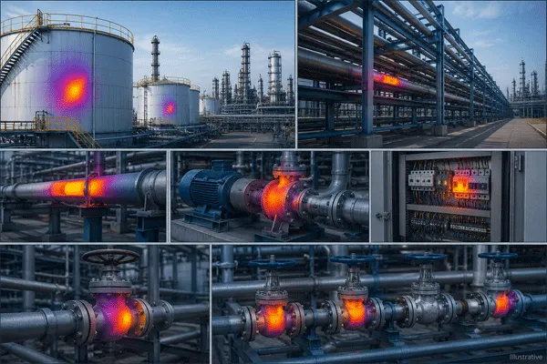
Online Thermal Monitoring for a Chemical Industry Park (Illustrative)
Project Objectives
Establish continuous remote observation of selected critical equipment and areas.
Detect abnormal heat patterns and threshold violations earlier.
Combine thermal images with visible-light video for alarm verification.
Centralize alarms from multiple monitoring points.
Store thermal events and historical records for later review.
Complement, rather than replace, existing process instruments, fire detection, gas detection and maintenance inspection.
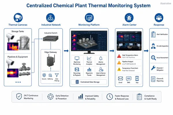
Recommended Engineering Architecture for Similar Projects
Based on the public case description and Midradar’s current product portfolio, the following multi-layer architecture is recommended for comparable projects. It should not be read as a disclosure of the exact Yantai installation.
The thermal channel is used to identify temperature distribution, hot spots and abnormal thermal changes. The visible-light channel provides contextual images so that operators can determine which item is involved and whether the condition is credible.
Depending on the monitoring distance and target distribution, the system can use:
Wider-view thermal PTZ cameras for nearby equipment groups.
Longer-focal-length thermal PTZ cameras for distant or elevated assets.
Dedicated fixed thermal cameras for assets requiring uninterrupted observation.
Optional long-range fire and hot-spot detection cameras for open storage or boundary areas.
Layer 2: Edge Analysis and Alarm Rules
Each monitored scene is divided into relevant measurement areas.
Depending on the application, alarm rules may include:
Maximum temperature threshold.
Minimum temperature threshold.
Temperature difference between two areas.
Abnormal temperature rise.
Regional hot-spot detection.
Equipment-specific warning levels.
Time-based alarm persistence.
Visible-light or operator confirmation before escalation.
Thresholds should be configured separately for different asset types and operating states. A pump bearing, electrical cabinet, tank surface and process pipeline should not share one universal alarm value.
Layer 3: Industrial Network and Data Transmission
Thermal video, visible-light video, temperature information, device status and alarms are transmitted to the monitoring centre through the site communication network.
For a large chemical park, the communication design may include:
Industrial Ethernet.
Fibre-optic backbone.
Managed network switches.
Segmented device networks.
Redundant transmission routes.
Lightning and surge protection.
Backup power for critical monitoring nodes.
Network architecture should be coordinated with the customer’s cybersecurity, IT and industrial-control requirements.
Online Thermal Monitoring for a Chemical Industry Park (Illustrative)
Layer 4: Centralized Thermal Monitoring Platform
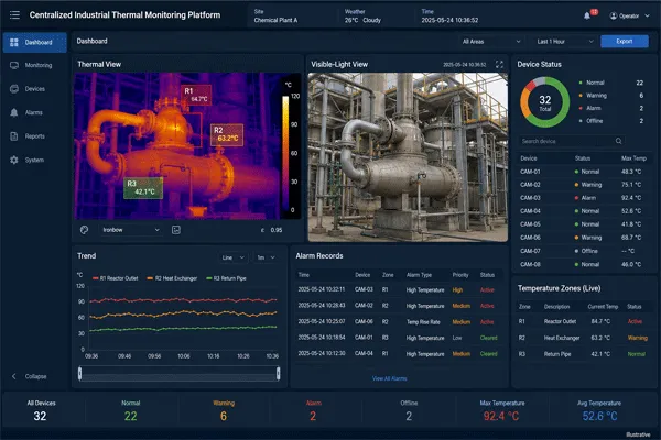
The centralized platform receives data from multiple field devices and presents the information through a unified interface.
Recommended platform functions include:
Live thermal and visible-light display.
Point, line and area temperature display.
Equipment and camera mapping.
Configurable alarm thresholds.
Alarm pop-up and sound notification.
Thermal and visible-image linkage.
Alarm acknowledgement.
Event classification.
Historical temperature curves.
Image and video storage.
Inspection reports.
User and permission management.
Device health monitoring.
Interface support for other safety or maintenance systems.
Layer 5: Operational Response
Confirmed thermal alarms are transferred into a structured handling process.
Depending on severity, the event may be sent to the central control room, maintenance department, production unit, safety department or emergency-response team.
The response process should define who receives each alarm, how quickly it must be reviewed and what information must be recorded before the event is closed.
Recommended Monitoring Workflow
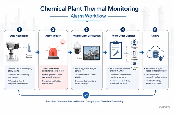
Step 1 — Automatic Monitoring
Thermal cameras continuously monitor selected process equipment, storage facilities, pipelines, valves, electrical systems and hazardous areas. PTZ cameras can follow preset patrol routes when one device is responsible for several monitoring points. Critical equipment requiring uninterrupted observation should be assigned a fixed view or a dedicated camera.
Step 2 — Thermal Data Capture
The system captures thermal images and temperature information for defined measurement regions. Operators can use different areas within one image to monitor separate components, such as a pump motor, bearing housing, coupling and adjacent pipeline.
Step 3 — Alarm Rule Trigger
The system compares measured conditions with the configured alarm rules. When a temperature threshold, hot spot, regional anomaly or abnormal change is detected, the platform creates an alarm event.
Step 4 — Visible-Light Verification
The visible-light channel is linked to the thermal alarm. Operators can check the physical scene, confirm the monitored asset and look for other indicators such as smoke, leakage, personnel activity, obstruction or changing process conditions.
Step 5 — Event Assessment
The operator reviews the thermal image, visible-light image, current temperature information, historical temperature trends, equipment operating condition and related process or maintenance information. The event is then classified according to the customer’s alarm-management procedure.
Step 6 — Dispatch and Handling
If the abnormal condition is confirmed, the operator notifies the responsible production, maintenance or safety team. The platform records the event time, monitored area, alarm level, images, video and handling status.
Step 7 — Review and Optimization
After the event is closed, the customer can review whether the alarm threshold was appropriate, the emissivity setting was correct, the camera view was obstructed, the monitoring region covered the correct component, weather or reflections affected the reading, and the operating procedure should be adjusted. This feedback process helps improve monitoring accuracy over time.
Typical Monitoring Objects
Storage Tanks
Thermal cameras can observe tank surfaces, roof areas, breathing valves, flame arresters, nozzles and selected accessories. The purpose is not to infer the complete internal process condition from a surface image. Instead, the system identifies visible thermal changes and abnormal patterns that require further investigation.
Pipelines, Valves and Flanges
Thermal monitoring can help identify unusual heat distribution, damaged insulation, heat loss or abnormal conditions around valves, flanges and pipeline connections.
Pumps, Compressors, Motors and Bearings
Rotating equipment may develop localized heating caused by friction, lubrication problems, electrical loading or cooling limitations. Thermal trends can provide an additional condition-monitoring indicator for maintenance personnel.
Reactors and Heat-Transfer Equipment
Reactors, furnaces, heat exchangers and condensers may require equipment-specific monitoring regions and thresholds. Camera placement should avoid obstructions and should account for normal process-temperature variation.
Electrical Equipment
Electrical cabinets, cable connections, distribution equipment and transformer-related components may be monitored for abnormal thermal concentration. Electrical inspection procedures and site safety rules still apply.
Unmanned and Restricted Areas
Remote thermal monitoring is particularly useful where routine access is difficult, limited or undesirable. The system can provide continuous visibility while reducing unnecessary personnel entry into selected areas.
Online Thermal Monitoring for a Chemical Industry Park (Illustrative)
Recommended Product Configuration for Similar Projects
The exact configuration must be determined through a site survey, target-pixel calculation, temperature-range review and hazardous-area assessment. The models below are recommended candidates for comparable projects; they are not confirmed as the products used in the Yantai project.
MR-DMS10-4200-50 Thermal PTZ Camera
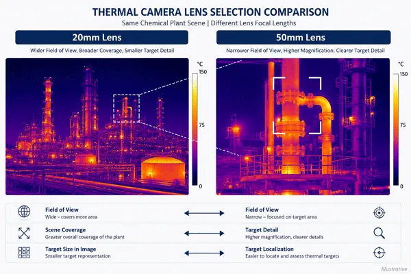
En MR-DMS10-4200-50 Thermal PTZ Camera is the strongest currently verified Midradar candidate for longer-distance quantitative temperature monitoring because its public page discloses a complete temperature range and accuracy specification.
Its 50 mm thermal lens is suitable for observing smaller or more distant targets than a wider-view configuration. The system supports thermal and visible-light imaging, configurable temperature measurement, alarm thresholds and pan-tilt patrol.
Recommended applications include:
Distant storage-tank accessories.
Elevated process equipment.
Long pipeline corridors.
Pump or utility areas observed from a safe stand-off position.
Remote monitoring points where detailed visible-light verification is also required.
The published product specification includes two optional temperature ranges, from -20°C to +120°C and from -20°C to +550°C, with stated measurement accuracy of ±2°C or ±2% of the selected range.
This recommendation does not establish actual deployment in the Yantai project, suitability for every chemical process, or hazardous-area certification. Final use depends on target pixel coverage, surface emissivity, viewing conditions, calibration and the exact certified product configuration.
The final temperature range should be selected according to the normal operating temperature and expected abnormal condition of the monitored asset.
Its 20 mm thermal lens is more appropriate when one camera must observe several nearby targets or a broader section of a process area.
Recommended applications include nearby pump groups, valve manifolds, electrical equipment areas, compact process units, loading areas and multi-point preset patrol at shorter stand-off distances.
The model supports full-screen, line and area temperature measurement, alarm thresholds and remote configuration.
The currently accessible public page does not disclose a complete measurement range or accuracy specification for this model. Do not copy the MR-DMS10-4200-50 temperature range or accuracy into the MR-DMS10-4200-20 description unless the manufacturer supplies a model-specific datasheet.
MR-DMS10-4300-50 Fire and Hot-Spot Monitoring Camera
It supports thermal and visible imaging, hot-spot detection, smoke and fire alarms, extensive preset patrol and intelligent event analysis.
Recommended applications include open storage yards, large tank-farm overview, remote material storage areas, vegetation or external fire-risk areas, and wide-area auxiliary fire monitoring.
Because the publicly available product page does not provide the same complete radiometric accuracy specification as the MR-DMS10-4200-50, it should not replace a dedicated temperature-measurement camera where accurate asset-level thermometry is required.
Online Thermal Monitoring for a Chemical Industry Park (Illustrative)
A camera that can detect a large object at several kilometres may still be unsuitable for accurate temperature assessment of a small valve or bearing at that distance.
Final selection should therefore be based on target-level thermal resolution and measurement requirements rather than general surveillance detection range alone.
Deployment Recommendations
Use Elevated Positions with Clear Lines of Sight
Cameras should be installed where structures, pipes, vegetation, steam and moving equipment do not repeatedly block the monitored targets. Elevated mounting can improve coverage, but excessive height or steep viewing angles may reduce the quality of surface-temperature measurement.
Separate Patrol Monitoring from Continuous Monitoring
PTZ preset patrol is useful when one camera must cover multiple assets. However, a PTZ camera cannot observe every preset at the same time. Assets requiring uninterrupted monitoring should use dedicated fixed views or separate cameras.
Define Asset-Specific Measurement Regions
Measurement areas should correspond to real components, not arbitrary rectangles covering an entire scene. Each region should have an identifiable asset name, expected operating range, warning threshold and alarm priority.
Establish Baselines Before Setting Final Alarms
The commissioning team should record equipment temperatures under representative operating conditions before final thresholds are approved. Baseline data should account for equipment load, production status, ambient temperature, time of day, weather conditions and seasonal variation.
Use Visible-Light Verification
Thermal alarms should be linked with visible images whenever possible. This improves operator understanding and helps distinguish equipment abnormalities from temporary environmental effects.
Review Hazardous-Area Requirements
Any camera, junction box, power unit, communication device or accessory installed inside a classified hazardous area must comply with the certification and protection requirements applicable to that location. Standard outdoor IP protection is not equivalent to explosion protection.
Engineering Limitations
Infrared thermography is a valuable condition-monitoring and early-warning tool, but its measurements require correct configuration and interpretation.
Measurement results may be affected by:
Surface emissivity.
Reflected apparent temperature.
Target distance.
Viewing angle.
Atmospheric attenuation.
Rain, fog, steam and dust.
Infrared-transparent windows.
Surface contamination.
Solar loading.
Camera calibration.
Insufficient thermal pixels on the target.
Reflective metal surfaces are particularly challenging because the apparent thermal image may contain reflected radiation from the sky, sunlight, nearby equipment or personnel.
For this reason, thermal monitoring should not be presented as a replacement for process temperature instruments, safety instrumented systems, fire detectors, gas detectors, pressure and flow instruments, electrical protection, mechanical inspection or qualified maintenance assessment.
It is a complementary visual and temperature-based monitoring layer that helps identify where further investigation may be required.
Publicly Reported Value and Expected Operational Benefits
The public case page describes a move from fragmented observation toward continuous monitoring, earlier warning and centralized management. The benefits below are consistent with that description and with the expected operational value of a correctly engineered thermal-monitoring system; they are not presented as independently measured KPIs for this project.
Continuous Visibility
Critical areas could be observed remotely rather than relying only on periodic patrols.
Earlier Abnormal-Condition Awareness
Thermal images and configurable alarms provided an additional opportunity to identify developing abnormal conditions.
Improved Alarm Verification
Visible-light linkage and historical records helped operators assess thermal events more systematically.
Centralized Management
Multiple monitoring points could be managed through a unified operational interface instead of operating as isolated devices.
Traceable Records
Thermal images, visible video, alarm information and handling records could support maintenance review and event investigation.
Scalable Architecture
Additional cameras and monitoring areas can be added as the customer expands the programme to new production units, pipelines, storage facilities or electrical systems.
The publicly available project information does not disclose device quantities, measured reductions in incidents, false-alarm statistics or maintenance-cost savings. These values should only be added after they are verified through project acceptance records or customer authorization.
Standards and Good-Practice Considerations
Industrial thermography programmes should establish documented procedures for monitored asset identification, baseline collection, emissivity configuration, alarm criteria, measurement repeatability, operator competence, reporting, calibration, data retention and periodic review.
For machinery condition monitoring, ISO 18434-1:2008 provides relevant guidance on infrared thermography procedures, anomaly assessment, reflected temperature, emissivity, attenuating media and reporting.
For equipment installed in potentially explosive atmospheres, the required hazardous-area classification and product certification must be confirmed before deployment. Depending on the market and project, IECEx, ATEX or applicable national certification requirements may apply.
Preguntas frecuentes
Can thermal cameras replace contact temperature sensors?
No. Thermal cameras provide non-contact surface-temperature information and broad thermal context. Contact sensors and process instruments may provide more direct or application-specific measurements. The two methods should be used as complementary sources when appropriate.
Can one PTZ camera monitor several tanks or process units?
Yes. A PTZ camera can follow a programmed preset route and inspect several targets. However, each target is only observed when the camera is directed toward it. Critical assets requiring uninterrupted observation should use dedicated views.
How should temperature alarm thresholds be set?
Thresholds should be based on equipment design, normal operating data, ambient conditions, process requirements and maintenance experience. One universal temperature threshold should not be applied to unrelated asset types.
Can the system identify smoke or fire?
Certain thermal-camera configurations support hot-spot, smoke and fire alarm functions. These capabilities can strengthen situational awareness but should not replace the site’s certified fire-detection and emergency systems.
Can the system integrate with an existing VMS, SCADA or maintenance platform?
Integration depends on the required interface, protocol, cybersecurity policy and customer system architecture. The interface scope should be confirmed during project design rather than assumed from basic video compatibility.
Are the recommended cameras explosion-proof?
The standard public product pages reviewed for this solution do not establish that every recommended configuration carries IECEx, ATEX or another hazardous-area certificate. Certification must be confirmed for the exact model, enclosure and installation location before the product is specified inside a classified zone.
What information is required to design a thermal monitoring system?
The minimum design inputs include site layout, equipment list, target dimensions, target distances, expected temperature ranges, hazardous-area classification drawings, required certifications, existing camera and platform infrastructure, network and power availability, alarm workflow and data-retention requirements.
Request a Chemical-Plant Thermal Monitoring Design
Send Midradar your site layout, equipment list, target distances, expected temperature ranges, hazardous-area classification and platform-integration requirements through a chemical-plant thermal monitoring design request.
Our engineering team will evaluate camera positions, thermal lens selection, measurement regions, alarm architecture and network requirements for your project.
Le responderemos en un plazo de 24 horas. Si se trata de un caso urgente, añada nuestro WhatsApp/WeChat: +86 15954290051, o llame directamente al +86 15964215221.
*Respetamos su confidencialidad y toda la información está protegida.
Solo utilizaremos su información para responder a su consulta y nunca enviaremos correos no solicitados ni mensajes promocionales.