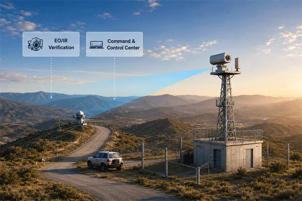
A pan-tilt unit is often selected from one headline parameter: maximum payload. That approach is acceptable for a small indoor camera, but it is inadequate for a long-range EO/IR system, radar-cued tracker or heavy outdoor sensor package.
The PTU must accelerate and stop a payload with a defined center of gravity and moment of inertia, hold line of sight in wind, move smoothly at very low speed, reach commanded angles without excessive overshoot, report its position accurately and survive the site environment. These requirements interact. Increasing speed, payload offset or wind area can reduce pointing stability and service life.
This guide explains the information an integrator should provide and the tests a supplier should complete before a PTU is approved.
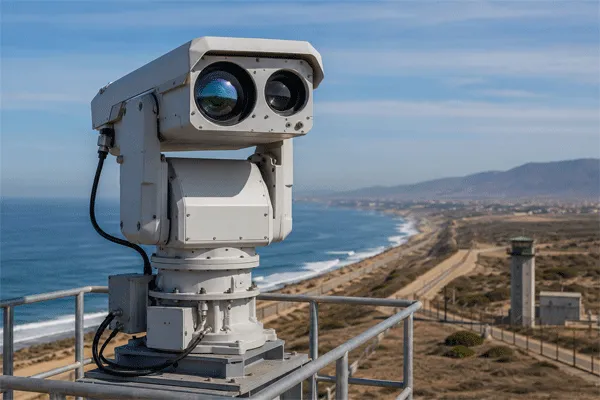
How to Select a Pan-Tilt Unit for Long-Range EO/IR and Radar-Cued Tracking
1. Payload Weight Is Only the First Input
Two payloads can both weigh 30 kg but create very different mechanical demand:
- Payload A is compact and balanced around the tilt axis.
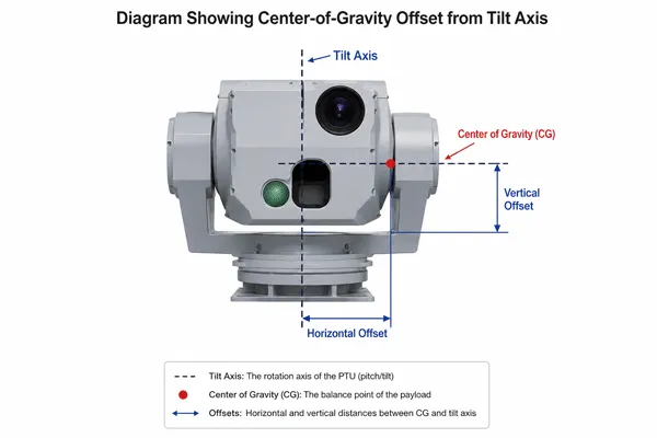
- Payload B uses a long telephoto lens, thermal camera, laser illuminator and protective housing, with its center of gravity 300 mm from the axis.
- Payload B has higher static moment, higher rotational inertia, larger wind area and greater structural flex.
- During acceleration or emergency stopping, the difference becomes more severe.
A serious PTU data request should therefore include mass, center-of-gravity coordinates, outer dimensions, projected wind area and inertia—or enough CAD information for the supplier to calculate them.
2. Center of Gravity and Static Moment
When the center of gravity is offset from the tilt axis, gravity creates a continuous torque. A first-order estimate is:
Gravity / imbalance torque ≈ Payload Mass × 9.81 × CG Offset
Example: 30 kg × 9.81 m/s² × 0.30 m ≈ 88 N·m |
This is before friction, acceleration, wind or safety margin. Counterbalancing the payload can dramatically reduce the continuous torque requirement and improve low-speed control, motor heating and gearbox life.
3. Moment of Inertia Controls Acceleration
Rotational inertia describes how strongly the payload resists angular acceleration. Mass located far from the axis contributes disproportionately. The dynamic torque required to accelerate the payload is approximately:
Acceleration Torque = Moment of Inertia × Angular Acceleration
Total Required Torque = Acceleration + Imbalance + Friction + Wind + Safety Margin |
A supplier cannot reliably determine acceleration performance from total weight alone. For rapid radar cueing, the time required to move through a given angle and settle within the pointing tolerance is more useful than no-load maximum speed.
4. Maximum Speed Is Not Tracking Quality
A PTU that rotates quickly can still perform poorly when tracking a slow or maneuvering target. Important motion specifications include:
| Parameter |
Why it matters |
| Maximum slew speed |
Determines gross repositioning time, but not settling or tracking smoothness. |
| Minimum stable speed |
Critical for smooth long-range tracking without stick-slip or visible stepping. |
| Acceleration and deceleration |
Controls time-to-target, overshoot and mechanical stress. |
| Speed resolution |
Determines how finely the controller can match target angular rate. |
| Settling time |
Time required to enter and remain within a defined pointing-error band. |
| Duty cycle |
Indicates whether high-speed operation can be sustained without overheating. |
For radar-cued tracking, request a move-and-settle test using representative angles and the actual payload—not an unloaded motor-speed value.
How to Select a Pan-Tilt Unit for Long-Range EO/IR and Radar-Cued Tracking
5. Pointing Accuracy, Repeatability and Resolution Are Not the Same
| Term |
Meaning |
| Command resolution |
Smallest angle step that the controller can request or represent. |
| Encoder resolution |
Smallest position increment measured by the feedback device. |
| Absolute pointing accuracy |
Difference between commanded and actual line of sight across the operating envelope. |
| Repeatability |
Ability to return to the same position under the same approach conditions. |
| Backlash / hysteresis |
Position difference caused by direction reversal and mechanical compliance. |
| Stabilized jitter |
Short-term line-of-sight motion while nominally stationary or tracking. |
A system can advertise very fine encoder resolution while still having poor absolute pointing accuracy because of gearbox backlash, structural deflection, assembly tolerance or boresight error.
Long focal length magnifies angular error. At 5 km, an angular error of 0.1° corresponds to approximately 8.7 m of lateral displacement. This is why radar-cued systems require an end-to-end error budget rather than a PTU datasheet value in isolation.
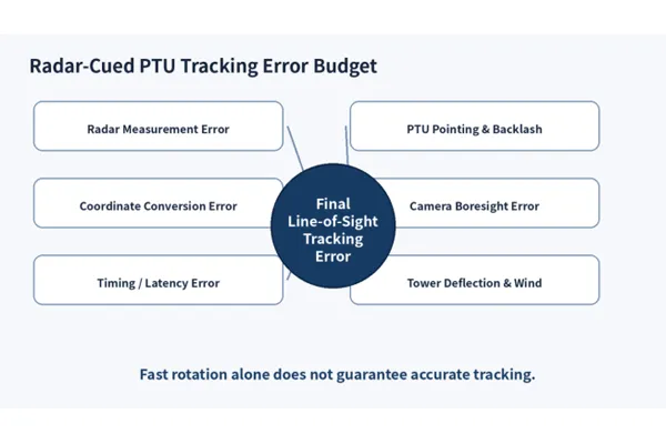
Final tracking error is the sum of sensor, timing, conversion, mechanical and boresight contributions
6. Wind Load and Structural Deflection
Outdoor payloads act like sails. Wind torque depends on projected area, drag coefficient, wind speed and distance from the rotation axis. Because aerodynamic force increases approximately with the square of wind speed, a system that is stable in a moderate breeze may become unusable in a strong gust.
The design review should include:
- Maximum operational wind for full performance.
- Survival wind when the unit is parked or locked.
- Projected area from multiple azimuths and elevation angles.
- Mast, tower and mounting-plate stiffness.
- Natural frequency and potential resonance with motor commands or wind excitation.
- Cable drag, housing flex and lens-support stiffness.
- Image-based jitter measured with the real focal length.
A mechanically strong PTU mounted on a flexible pole will still produce unstable imagery. The foundation, mast, adapter and payload are part of the line-of-sight system.
7. Radar-Cued Tracking Requires an End-to-End Error Budget
Radar-to-camera cueing combines multiple coordinate systems and time references. The final line-of-sight error can include:
- Radar range and angular measurement error.
- Radar position and orientation-survey error.
- Geodetic-to-local coordinate conversion error.
- Target-motion prediction and network latency.
- PTU absolute positioning and backlash.
- Camera-to-PTU boresight error.
- Structural deflection and wind-induced vibration.
- Timestamp misalignment between radar, controller and video.
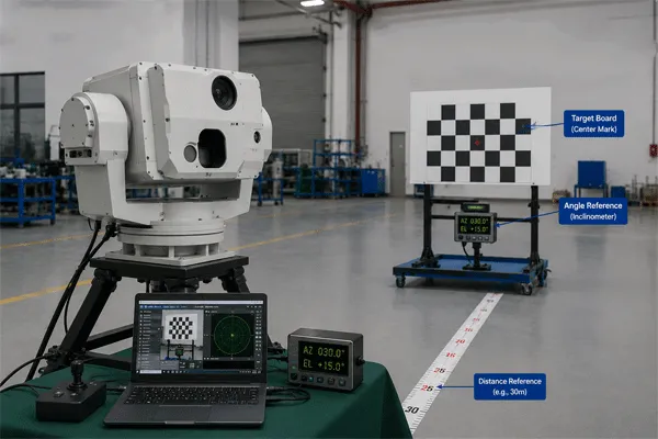
The commissioning process should use surveyed reference points or cooperative targets to calibrate boresight and transformation parameters. Calibration should be checked at multiple azimuth and elevation angles, because a single correction at one point may not represent the full operating envelope.
8. Interfaces, Feedback and Interoperability
The interface specification should identify both command transport and functional behavior. Common options include Ethernet, RS-422/485, Pelco-D/P, ONVIF and manufacturer APIs.
For radar cueing, the following functions are particularly important:
- Absolute pan and tilt positioning, not only left/right/up/down speed commands.
- Real-time position feedback with timestamps.
- Command acknowledgement and fault reporting.
- Configurable acceleration, speed and soft limits.
- Preset and patrol functions where required.
- Time synchronization through NTP, PTP or a defined system clock.
- API access for calibration offsets and coordinate mapping.
- Cybersecurity controls, authentication and secure transport.
ONVIF Profile T covers advanced IP-video functions and makes PTZ control mandatory for conformant clients, while also addressing PTZ configuration and related streaming/event features. A project should verify the exact ONVIF profile and the product’s conformant status rather than accepting a generic “ONVIF supported” statement.
9. Environmental and Lifecycle Requirements
An IP rating describes enclosure protection against solid objects and water under defined tests. It does not by itself prove salt-fog resistance, corrosion life, de-icing capability, shock survival or reliable operation at temperature extremes.
| Requirement |
Questions to specify |
| Ingress protection |
Which IEC 60529 IP level applies, and does it cover the complete assembled system and connectors? |
| Temperature |
Operating, storage and cold-start temperatures; internal heater or fan behavior. |
| Salt fog / corrosion |
Coating system, material compatibility and test duration for coastal sites. |
| Wind and ice |
Operational/survival wind, ice loading and de-icing strategy. |
| Shock and vibration |
Vehicle, tower or mobile-platform profile and test standard. |
| Lightning / surge |
Grounding, surge protection and network isolation. |
| Maintenance |
Lubrication interval, seals, slip-ring life, motor/gearbox replacement and remote diagnostics. |
10. Factory and Site Acceptance Tests
A useful acceptance program combines mechanical, control and image-based tests:
| Test |
Suggested measurement |
| Payload verification |
Actual mass, center of gravity, dimensions and cable routing. |
| Slew and settle |
Time to move through defined angles and settle inside the required error band. |
| Minimum-speed tracking |
Image smoothness and angular-rate stability at very low speed. |
| Repeatability |
Return error after approaching presets from both directions. |
| Absolute accuracy |
Measured pointing error across an azimuth/elevation grid. |
| Backlash |
Error introduced by direction reversal under representative load. |
| Wind performance |
Pointing/jitter under an agreed wind condition or validated structural model. |
| Thermal endurance |
Duty cycle and motor/controller temperature during repeated operation. |
| Interface latency |
Command-to-motion and position-feedback latency. |
| Radar cueing |
End-to-end acquisition time and line-of-sight error using moving targets. |
| Environmental inspection |
Seals, connectors, drainage, coating, grounding and cable strain relief. |
How to Select a Pan-Tilt Unit for Long-Range EO/IR and Radar-Cued Tracking
11. PTU Selection Data Sheet
Before requesting a quotation, provide the following data:
- Payload mass and component list.
- Center of gravity relative to pan and tilt axes.
- Payload CAD or dimensions and projected wind area.
- Required pan/tilt travel and cable-management method.
- Maximum slew speed, minimum tracking speed and acceleration.
- Required absolute accuracy, repeatability, settling time and jitter.
- Operating and survival wind.
- Temperature, salt fog, rain, dust, ice, shock and vibration conditions.
- Power supply and maximum power budget.
- Required interfaces, API, feedback frequency and cybersecurity.
- Mounting arrangement and tower/foundation data.
- Acceptance-test procedure and duty cycle.
12. Applying the Method to Midradar PTU Products
Midradar’s PTU portfolio includes single-axis units, dual-axis pan-tilts, rotary platforms and heavy-load systems. The product range covers compact sensor packages as well as large EO/IR assemblies.
For OEM or integrated projects, the model should be selected from the complete load case. Midradar can evaluate payload weight, center of gravity, wind area, speed, pointing requirements and control interfaces, then recommend a standard or customized platform.
FAQ
Can I select a PTU only by maximum payload weight?
No. Weight is only one input. Center-of-gravity offset, inertia, wind area, acceleration, duty cycle and pointing accuracy can be equally important.
What is more important: pointing accuracy or repeatability?
They answer different questions. Accuracy measures how close the system is to the commanded line of sight; repeatability measures whether it returns consistently. Radar cueing usually needs both.
Why does a long lens make PTU selection harder?
A long lens increases payload length, inertia and wind area while magnifying angular vibration and pointing error in the image.
Does IP66 mean the PTU is suitable for coastal deployment?
Not by itself. Coastal suitability also requires corrosion materials/coatings, sealed connectors, drainage, salt-fog validation and maintenance planning.
Should radar and PTU use the same time source?
Yes, synchronized timestamps reduce target-prediction and coordinate-conversion error, particularly for fast or maneuvering targets.



 09:38
09:38