Executive Summary
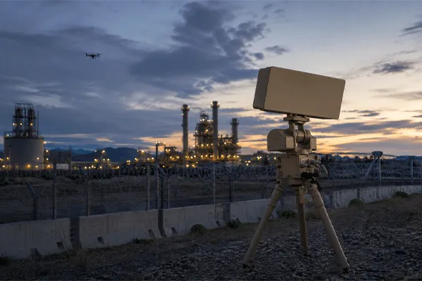
This is a sensor-role and evidence-association guide, not a C2 interface specification. Radar, RF detection and EO/IR produce different observations and should not be scored as interchangeable sensors. Radar provides non-cooperative detection, position and motion tracks. RF systems may add emitter, protocol or bearing evidence when a relevant transmission is present. EO/IR provides visual or thermal verification and recorded evidence. A C2 platform associates the observations, manages confidence and priority, and preserves the event history.
Fusion is successful when the system forms a timely, traceable and operationally useful event without converting correlation into an unsupported identity claim. The architecture must define sensor roles, association rules, confidence transitions, verification criteria, degraded modes and evidence retention. For pre-selection comparison, use the radar EO fusion procurement checklist. Detailed track fields, coordinates, timestamps, device-control commands and EO/IR cueing acceptance belong to the separate Counter-UAS C2 interface requirements guide. MR2000 provides a practical Midradar basis for unified device management, multi-source fusion, radar-to-EO/IR cueing, alarms, unattended operation and historical replay.
Counter-UAS Sensor Fusion: Radar, RF and EO/IR Roles, Association and Verification
Key Questions This Guide Answers
- Why should radar, RF detection and EO/IR be assigned different roles?
- Can RF detection replace non-cooperative radar detection?
- How are observations associated without turning correlation into a false identity claim?
- How should observations be associated and confidence updated without overstating identity?
- How should false association, degraded mode and event evidence be accepted?
Applicability and Fusion Boundary
This guide applies to projects that use radar, RF and EO/IR as complementary sources in one C2 workflow. It does not assume that all projects require every sensor or that a fused label is automatically correct. The architecture should preserve original observations, quantify uncertainty and permit an operator to review the evidence. Active response functions, where legally authorized, remain a separate subsystem and approval path. Actual sensor models, interfaces, association rules and acceptance thresholds must be selected for the site and mission.
1. Assign Clear Sensor Roles
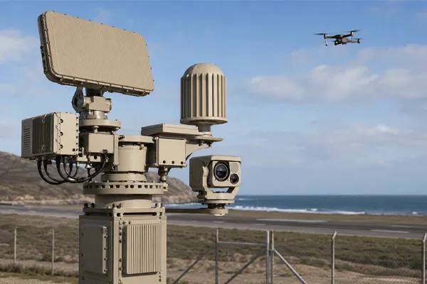
Radar is normally the primary wide-area sensor for non-cooperative objects because it measures range, direction and motion without requiring the target to transmit. RF detection can add protocol, emitter or bearing information, but autonomous, pre-programmed or RF-silent targets may not provide a usable signal. EO/IR can confirm shape, behavior and context, but its field of view, atmosphere, lighting and line of sight limit wide-area search.
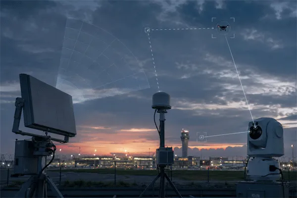
The architecture should use each sensor for its strongest role. Radar discovers and tracks. RF adds electronic evidence when available. EO/IR verifies and records. C2 manages association, priority, workflow and evidence. Stating these boundaries reduces unrealistic expectations and prevents one sensor from being evaluated against the wrong task. For the complete workflow, review the integrated counter-UAV architecture.
Sensor Role and Evidence Matrix
| Layer |
Primary Contribution |
Key Limitation and Acceptance / 主要限制与验收 |
| Radar |
Non-cooperative detection, position, velocity and track continuity |
Test clutter, minimum range, update behavior, track ID and geometry |
| RF / RF |
Emitter, protocol or bearing evidence when transmissions are present |
RF-silent targets, spectrum environment, legal boundary and false association |
| EO/IR |
Visual/thermal verification, tracking and recorded evidence |
Line of sight, atmosphere, field of view, cueing error and identification confidence |
| C2 and fusion |
Association, priority, cueing, uncertainty, event and operator workflow |
Time/coordinate control, explainability, degraded mode and audit trail |
2. Observation Association Is Not Simple Overlay
Two detections should not be fused merely because they appear close on a map. The system should consider time, position uncertainty, velocity, bearing, target class, sensor coverage and track history. A radar track and an RF bearing may support the same event without producing the same position accuracy. EO/IR confirmation may belong to a track only after cueing, target-in-frame validation and tracking feedback.
The fusion logic should preserve the original sensor observations as well as the fused event. Operators and investigators need to know which sensor contributed each conclusion and how confidence changed over time.
Counter-UAS Sensor Fusion: Radar, RF and EO/IR Roles, Association and Verification
3. Coordinate and Time Foundation
Every sensor must be located and oriented correctly. The project should define datum, altitude reference, units, north convention, sign, mounting coordinates and boresight calibration. When radar and EO/IR devices are separated, their true latitude, longitude and altitude must be used and coordinate conversion becomes part of the integration scope.
Time is equally important. Detection time, measurement time, update time, send time, device position and video time should use a defined common reference. Data age should be visible or calculable so the system can predict a moving target rather than cueing a camera to an old position. For detailed track fields, coordinate and time synchronization, device-control commands and EO/IR cueing acceptance, read Midradar’s Counter-UAS C2 interface requirements guide.
4. Detection-to-Verification Workflow
A robust workflow begins when the radar forms a stable track. The C2 checks quality and priority and determines whether an RF observation or other sensor report supports the event. It then selects an EO/IR device based on coverage, availability and task priority. Coordinate conversion and target prediction generate the cueing command. The PTU moves and reports position; the camera acquires, confirms or rejects the target; the result is attached to the event. For long-range cueing hardware selection, review the pan-tilt unit selection guide.
The workflow should define what happens when confirmation fails. The system may continue cueing, widen the search, select another camera, lower confidence, retain the radar-only event or alert an operator. Failure behavior is part of fusion design. Projects centered on radar cueing and visual verification can review the radar-vision fusion rapid-response guide.
5. MR2000 Functions in the Fusion Workflow
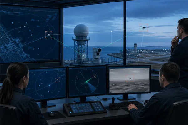
MR2000 supports unified management of radar, spectrum-detection, EO/IR and authorized response devices. It provides map display, target lists, multi-source track fusion, radar guidance of EO/IR, video monitoring and recording, electronic fences, alarm levels, role-based user management, automatic search and unattended operation. It can also replay tracks and synchronized video for historical review.
These functions support an integrated operating workflow. They do not eliminate project engineering. Device coordinates, radar and camera calibration, target-processing parameters, refresh behavior, target-loss rules, camera fields of view, tracking modes and unattended-response conditions must be configured and validated for the actual installation.
6. Common Integration Failure Modes
Frequent fusion failures include assigning overlapping or undefined sensor roles, associating observations only because icons are close on a map, treating an RF emitter identity as the physical target identity, replacing original observations with one opaque fused label, failing to record confidence changes, and continuing normal conclusions after a sensor becomes unavailable.
Another failure is conceptual: treating classification as certainty. Radar, RF or AI labels should carry confidence and supporting evidence. Visual confirmation can also remain ambiguous under long range, haze, low contrast or partial obstruction. The system should preserve uncertainty, show each sensor contribution and support operator review. Coordinate, timing, driver and device-control faults should be tested under the separate C2 interface acceptance plan rather than duplicated here.
Counter-UAS Sensor Fusion: Radar, RF and EO/IR Roles, Association and Verification
7. Fusion Logic and Operational Acceptance
Acceptance should test whether sensor roles and association logic create correct, traceable events. Use representative single- and multi-target scenarios, including RF-silent targets, an RF observation without a matching radar track, two tracks crossing, camera acquisition failure, a conflicting classification, sensor dropout and recovery. Measure correct association, false association, track-ID continuity, time to verification, confidence transitions, degraded-mode behavior and event-evidence completeness.
The exported record should preserve the original radar track, RF observation where applicable, EO/IR video or snapshots, fused-event decision, alarms and operator actions under a common event ID. Interface timing, coordinate conversion, command latency and target-in-frame error remain mandatory project tests, but their detailed specification belongs to the Counter-UAS C2 interface requirements guide.
Use the radar field-test and acceptance guide to define test geometry and responsibilities.
Conclusion and CTA
Multi-sensor fusion creates value when it converts different observations into a controlled decision and evidence workflow. The architecture must respect the limits of each sensor, preserve original data, manage time and coordinates, close the cueing loop and remain understandable during faults.
For a Midradar multi-sensor architecture review, provide the site and threat, existing radar/RF/EO/IR equipment, C2 or VMS, interface documents, network and cybersecurity requirements, operator workflow and acceptance targets. Midradar can prepare a preliminary sensor-role matrix, data-flow architecture and integration clarification list.
FAQ
Can RF detection replace radar?
Not for every threat. RF detection depends on relevant emissions; autonomous or RF-silent targets may require non-cooperative radar detection.
Does EO/IR identify every radar track?
No. Visual confirmation depends on line of sight, range, atmosphere, field of view, pointing accuracy, contrast and tracking performance.
What should be stored as event evidence?
At minimum, the original sensor observations, fused event, timestamps, track IDs, alarms, video or snapshots, operator actions and device status relevant to the event.
How should sensor association be tested?
Use representative single- and multi-target scenarios with known timing and geometry. Measure correct and false associations, track-ID continuity, conflict handling and preservation of original observations.
What should happen when one sensor becomes unavailable?
The C2 should report the fault, preserve available data, apply the agreed degraded workflow, prevent unsupported conclusions and record the failure and recovery sequence.



 09:42
09:42